Background technique:
The domestic fire extinguisher market is welded by rolling cylinders. The traditional process uses the steel plate to be cut into squares, and then the steel plate is rolled into a cylindrical shape with a rolling machine, and finally the longitudinal seam is welded. The operation of this process is relatively complicated, and there is an urgent need for a high-efficiency coiled tube welding equipment. The utility model patent No. cn210878536u discloses a dry powder fire extinguisher barrel welding production line, “The iron sheet is rolled into a round tube by the rolling mechanism 2 3. At the same time, the welding mechanism 5 performs butt welding (principle is the prior art)”, the drag force in the horizontal direction of the steel strip in this feeding mode is relatively concentrated, and it is easy to bend in the horizontal direction.
Technical realization elements:
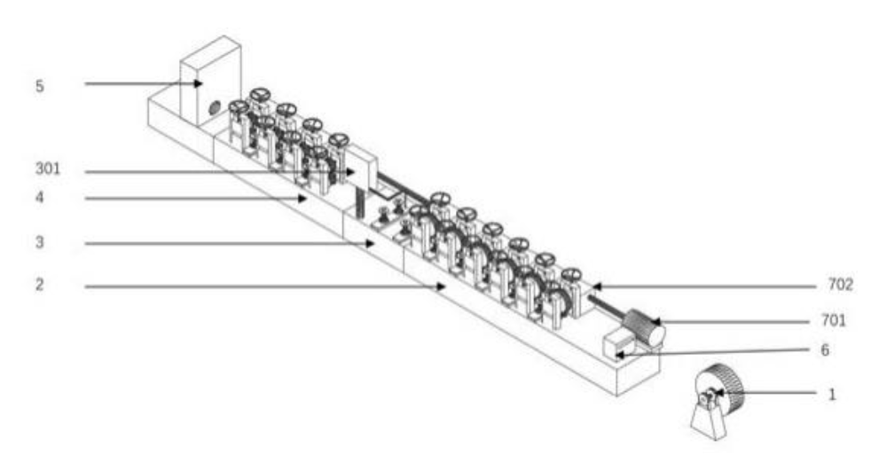
1. In view of the problems in the above-mentioned background technology, the utility model provides an automatic coil welding device for fire extinguishers, including: a welding device, and also includes: an unwinding machine, a coiling device, a cutting device, the uncoiling machine, the coiling device The device, the welding device and the cutting device are arranged along a straight line in order to form a production line. The coiling device rolls the steel coil material sideways into a cylindrical structure. A shaping device is installed between the cutting device and the welding device, which also includes: A driving device, the driving device includes: a motor installed on the end of the frame, a synchronous shaft installed on the motor shaft, and the synchronous shaft is used to make the coiling device and the sizing device drag the steel coil at the same speed.
2. As a preferred solution of the present utility model, the coiling device includes: a frame, a coiling wheel group, a flattening wheel group, and a steel coil limiting device, and the steel coil limiting device is installed on the machine The end of the frame is set close to the unwinding machine, the steel coil limit device is provided with a strip channel, the coiling wheel set and the flattening wheel set are installed on the frame and arranged at intervals, steel After passing through the strip channel, the roll enters the coiling wheel set and the flattening wheel set.
3. As a preferred solution of the present utility model, there are multiple groups of the coiled tube wheel set and are installed on the upper surface of the frame along a straight line, and the tube coiled wheel set consists of two vertically arranged coiled tubes Composed of rollers, the two rolling tube rollers are set vertically, the said rolling tube roller is a cylindrical body with a concave arc surface in the middle, and the distance between each group of rolling tube rollers gradually decreases from left to right on the frame .
As a preferred solution of the present utility model, the flattening wheel set includes: an upper pressing wheel and a lower pressing wheel, the upper pressing wheel and the lower pressing wheel are arranged facing up and down, and the middle part of the upper pressing wheel is arranged It is a concave arc surface structure, and the middle part of the lower pressing wheel is an outward convex arc surface structure.